Lpg Gas Flow Meter
Lpg Gas Flow Meter
The main technical parameters:
1. Applicable medium of JYLUGB vortex flowmeter: no corrosive liquid, ordinary gas, natural gas, steam (saturated steam and superheated steam);
2. Measuring flow range: liquid 0.3~7m/s, gas 3~55mm/s, steam 7~70m/s
3. The temperature of the measured fluid: -40℃~+350℃
4. Accuracy: 1%, 0.5% (0.5% can be achieved through nonlinear fine-tuning);
5. Repeatability: 0.2% of the indicated value;
6. Main body material: 304 stainless steel, 316 stainless steel
7. Pressure loss: △= 1.2×r×V2×10-6 where: △P fluid density measured by pressure loss r (Kg / m3) v-average flow velocity in the pipe (m / s)
8. Ambient temperature: -20℃~+55℃ (special requirements of ordering instructions)
9. External power supply: 3.6~224VDC
10. Signal output: pulse output (external power supply), current output 4-20mADC (two-wire external 24VDC power supply), 485 communication (optional).
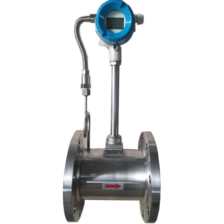
Outline structure drawing of LPG vortex flow meter

Vortex flow meter types

Flow range
| Instrument caliber(mm) | liquid | Gas | ||
Measuring range(m3/h) | Output frequency range(Hz) | Measuring range(m3/h) | Output frequency range(Hz) | |
15 | 0.3~5 | 24~400 | 4~20 | 352~1761 |
20 | 0.6~10 | 23~382 | 6~30 | 254~1273 |
25 | 1.2~16 | 21~320 | 8~55 | 161~1112 |
32 | 1.8~20 | 18~200 | 10~120 | 97~1172 |
40 | 2~40 | 10~190 | 27~205 | 134~1018 |
50 | 3~60 | 8~150 | 35~380 | 87~952 |
65 | 4~85 | 6~120 | 60~640 | 71~764 |
80 | 6.5~130 | 4.1~82 | 86~1100 | 54~696 |
100 | 15~220 | 4.7~69 | 133~1700 | 42~548 |
125 | 20~350 | 3.2~57 | 150~2000 | 26~346 |
150 | 30~450 | 2.8~43 | 347~4000 | 34~392 |
…… | ||||
300 | 95~2000 | 1.2~24 | 1360~18000 | 16~216 |
Installation conditions:
1. The sensor should be installed horizontally or vertically (the flow direction of the liquid is from bottom to top) on the pipe corresponding to its nominal diameter.
2.The upstream and downstream of the sensor should be equipped with a certain length of straight pipe, and its length should meet the requirements of the following table.
3.Straight pipe length configuration
Upstream pipeline form | Upstream straight pipe length | Downstream straight pipe length |
Concentric pipe fully open gate valve | ≥12DN | ≥5DN |
Concentrically retracted fully open gate valve | ≥15DN | ≥5DN |
One 90°C elbow | ≥20DN | ≥5DN |
Two 90℃ elbows on the same plane | ≥25DN | ≥5DN |
Two 90℃ elbows in different planes | ≥40DN | ≥5DN |
Regulating valve, semi-open gate valve | ≥50DN | ≥5DN |